MIDI DIY interface
You can use the serial interface (UART) of the PI for "talking MIDI" with:- devices to be connected with the DIN cables
- other microcontrollers like ESP, PICO or Arduino for adding special features/extensions.
Set the USE_SERIALPORT_MIDI parameter to TRUE to enable it.
See next paragraphs for some tech details regarding the standard midi wiring, the MIDI cables and the various types of cnnectors.
MIDI Interface Bus
 MIDI defines the electrical and physical interface over a 5-pin DIN connector, on a 64 ohm cable.
See Philip Rees docs for more tech details.
MIDI defines the electrical and physical interface over a 5-pin DIN connector, on a 64 ohm cable.
See Philip Rees docs for more tech details.
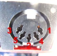
Pins 1 and 3 are never needed. Pin 2 is used for the shield, in order to ground the cable. That leaves the other two pins to carry an isolated current loop.
| MIDI out connection | MIDI in connection |
|---|---|
| pin 4 = -ve or sink | pin 4 = +ve or source |
| pin 5 = +ve or source | pin 5 = -ve or sink |
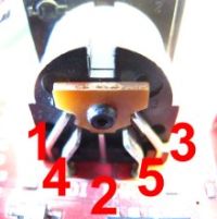
This is why all devices (instruments, controllers) have female sockets.
And all cables (except those explicitly designed as extension cables) have male plugs.
This ensures the correct electrical contacts without having to label ends.
IC Circuitry for the MIDI In, MIDI Thru and MIDI Out Interfaces
The full specs in CA33.pdf of the MIDI association drill down to next more simplified circuits: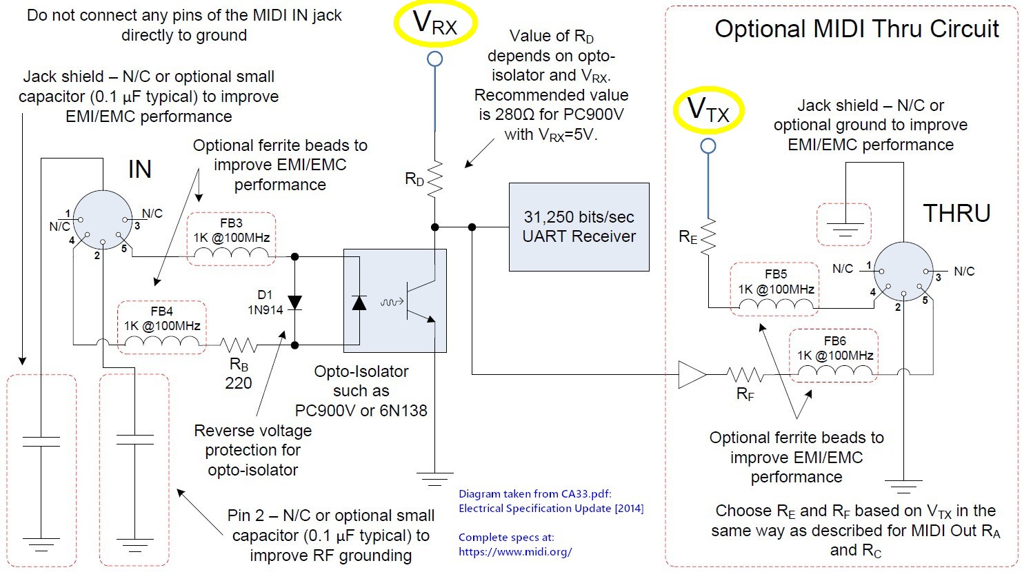
Actual 5-pin DIN chassis socket
The Mini DIN connector
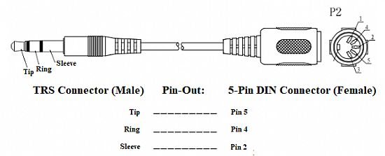
Many variations, this article gives good overview.The TRS connector
Please note this article as variations exist / manufacturer.